/ CIVIL · BRIDGE
Bridge Launching
Incremental launching of a bridge deck. Large custom pads hold friction steady over the full length of travel.
Large lubricating pads made and bonded to your drawing. While structures weighing hundreds of tonnes — bridge spans, plant modules, ship blocks — are moved, launched or repositioned, they hold friction steady and limit damage to the contact face.
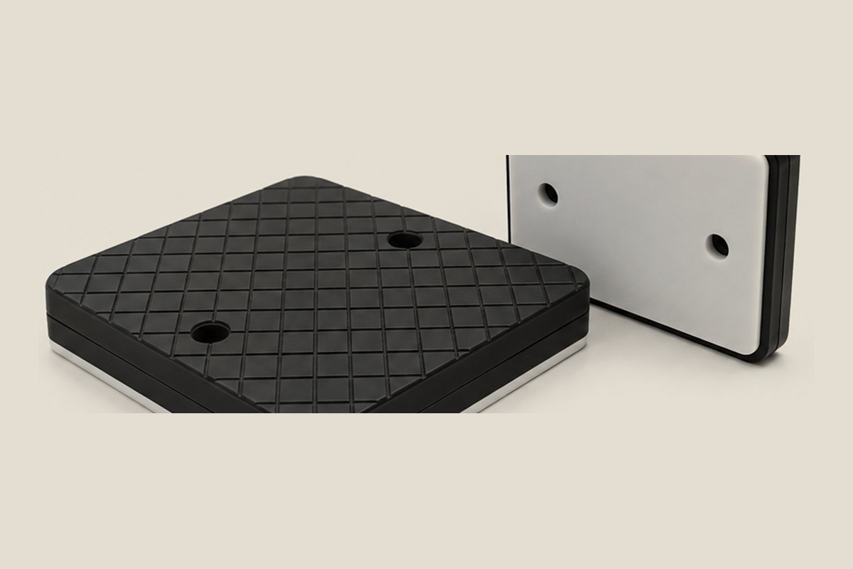
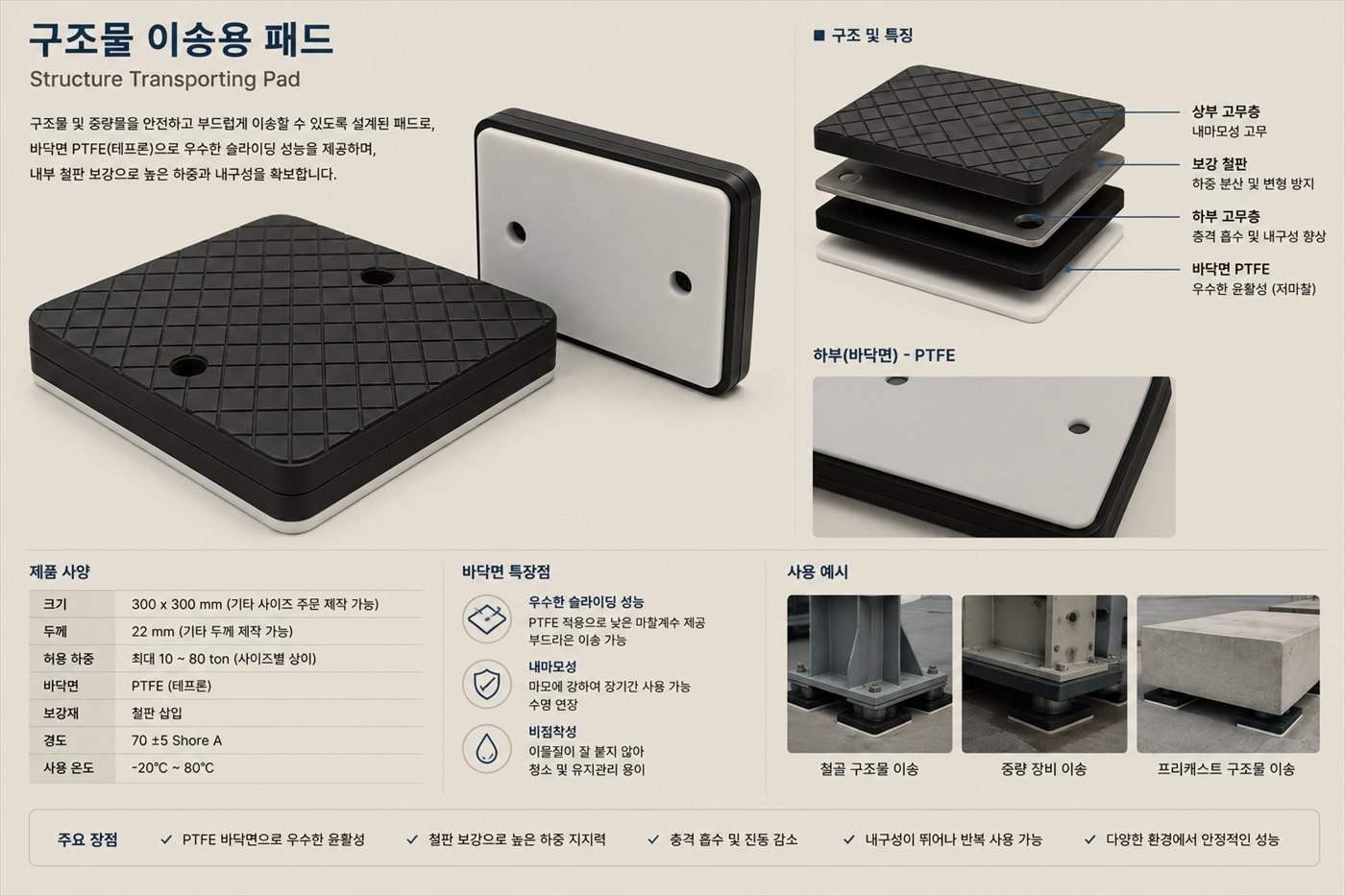
The table below describes a standard SKU. Every line is made to order against your drawing, load case and friction requirement. Ask us about special temperature or chemical duty.
| Property | Value | Note |
|---|---|---|
| Length (L) | Per drawing | Usual range · larger sizes bonded in sections |
| Width (W) | Per drawing | Per your drawing |
| Total Thickness (T) | Per drawing | Support plus PTFE combined |
| PTFE Lube Face | Per drawing | Virgin · filled · graphite — choose a grade |
| Bond Interface | Per drawing | Thermosetting |
| Support Substrate | Per drawing | Rust-preventive treated · material and thickness to specification |
| Coefficient of Friction (μ, dry) | Per drawing | At 10 MPa, room temperature |
| Operating Temperature | Per drawing | Wide range, PTFE based |
| Max Contact Pressure | Per drawing | Static load · local contact assessed separately |
| Surface Roughness (Ra) | Per drawing | PTFE sliding face |
| Edge Finish | Per drawing | As specified on the drawing |
| General Tolerance | Per drawing | Where not otherwise specified |
| Ordering Basis | Per drawing | Quoted on receipt of your drawing and specification |
A thermosetting adhesive joins the PTFE layer to the support. Large sizes are bonded in sections with a continuous joint.
Material, thickness and hole machining all follow your drawing, matched to the load and to the existing structure. Rust-preventive treatment before bonding secures adhesion.
Incremental launching of a bridge deck. Large custom pads hold friction steady over the full length of travel.
Repositioning and launching plant modules, ship blocks and power equipment within a yard. The pad is shaped to the travel path on your drawing.
Skid pads for precise horizontal movement of heavy equipment and precast structures. They carry hundreds of tonnes while limiting scratching and damage to the contact face.